
Designing the electrical path with conductive fabric and adhesive
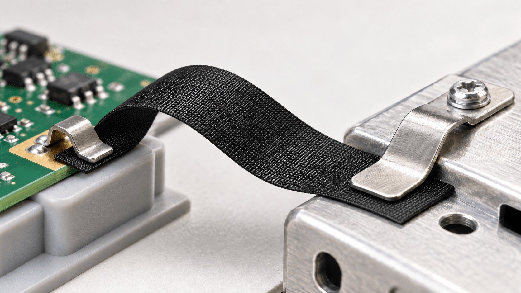
Illustrative flexible grounding concept, not an actual product photograph or a qualified assembly. Both contacts meet the exposed conductive fabric surface; the nonconductive adhesive is not the electrical path.
Selecting a conductive fabric starts with a practical question: where does the electrical path need to go? A design may need a connection along an exposed fabric surface, a connection through a bonded interface, or a conductive layer attached to a supporting surface. Those requirements call for different construction details.
P-SHIELD® PS-2748 provides a useful example. It combines nickel/copper-plated woven polyester with a black conductive coating and a nonconductive heat-activated adhesive. The conductive layers and the attachment adhesive have different roles. Understanding those roles helps you define the contacts, bonding process and tests the assembly needs.
Start with the layer construction
In PS-2748, the plated woven fabric and black conductive coating form the conductive portion of the construction. The nonconductive heat-activated adhesive provides attachment. When you draw the assembly, identify which material touches each face and where the intended electrical contacts will be made.

If your design requires an electrical connection to the mounting surface through the adhesive, that requirement deserves its own review. A conductive fabric surface does not establish a conductive bond through the adhesive beneath it. Show the intended route on the assembly drawing rather than treating the entire laminate as one electrically uniform material.
Read directional properties in context
The X and Y directions lie along the plane of the material. The Z direction runs through its thickness. These labels describe the direction being considered; they do not, by themselves, establish a material's electrical performance.
The PS-2748 technical data sheet reports surface resistivity below 0.05 Ω/sq using QSP-741. That value describes a surface property. A through-thickness connection involves a different path, including the adhesive and the contacts at the adjoining surfaces. Specify the resistance requirement for that complete path and evaluate it in the intended assembly.
Electrical isolation also needs its own requirement and supporting test data. A nonconductive adhesive description is not a dielectric-withstand rating. Where separation from a neighboring conductor matters, include the required isolation performance in the design and test criteria.
The same distinction applies to shielding. PS-2748's data sheet lists shielding effectiveness of 70–100 dB over 10 MHz–1.0 GHz. Treat this as material-level information for selection. Verify shielding performance in the finished assembly, with its actual contacts and geometry.
Match the adhesive to the assembly process
PS-2748's data sheet lists an adhesive activation range of 110–160 °C. Use that range to begin a discussion of the bonding process and the temperature limits of the surrounding parts. Establish suitable pressure, dwell time and process conditions with PSI, then validate the bond on the actual substrate. An activation-temperature range alone does not define a complete lamination cycle.
For comparison, P-SHIELD® PS-2708 and PS-2709 use gold-plated woven conductive fabric with a nonconductive acrylic adhesive. Their data sheets explicitly describe conductivity along the fabric surface in the X and Y directions. They provide another attachment approach to consider when developing the assembly process. Their surface-conductivity description should be read alongside the requirements for the complete contact path.
When the bonded interface must conduct
If the electrical path needs to pass through the bond, consider a construction that explicitly includes conductive adhesive. P-SHIELD® PS-1332 is a double-coated nickel/copper-plated conductive fabric with conductive acrylic pressure-sensitive adhesive. Its product description identifies conductivity in the X, Y and Z directions.
This makes PS-1332 a useful construction contrast with PS-2748. It does not remove the need to check the actual contact surfaces or establish acceptance criteria for the assembly. Directional conductivity also does not imply identical resistance in every direction.
What to consider when designing a flexible grounding solution
Design the grounding path, contacts and attachment together so the intended connection can be maintained through assembly and use.
- Electrical path and exposed interfaces. Mark connection points and the route between them. Keep PS-2748 contact areas exposed and accessible; do not rely on conduction through its nonconductive adhesive. Define end-to-end resistance and any isolation requirement.
- Contact geometry and force. Define overlap, area and contact force. Check whether alignment and assembly tolerances allow the surfaces to remain in contact without damaging the fabric.
- Mating materials and finishes. Identify substrates, plating and coatings. Assess contamination, oxidation and corrosion compatibility in the service environment; verify performance with the actual mating surfaces.
- Flexing and strain relief. Define bend geometry and repeated movement. Route and support the fabric to limit loads at contacts and bonded edges, then test under representative use conditions.
- Bonding and assembly conditions. Check bonding access, assembly sequence and nearby parts’ temperature limits. Establish pressure, dwell time and temperature with PSI; verify attachment to the actual substrate.
- Finished assembly validation. Set acceptance criteria for the complete grounding path. Measure after assembly, flexing and relevant environmental conditioning; check bond retention and any required isolation or shielding performance.
Discuss your application with Polymer Science
Explore PS-2748 product details and contact Polymer Science to discuss your electrical path, substrates and bonding process. Share an assembly drawing and your performance requirements so we can discuss the appropriate P-SHIELD® construction and evaluation plan.